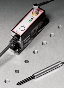
| Checks the presence or absence of threads using non-contact eddy current technology
Inductive ‘eddy current’ principles of operation
• An oscillating electro-magnetic field is produced in the sensor tip.
• Any conductive material engaging this field will have ‘eddy current’ induced in the surface setting up a corresponding electro-magnetic field.
• As the gap between the sensor and the conductive target material changes, the influence of the eddy current field on the sensor field changes.
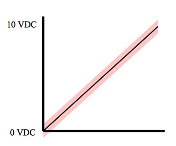
• The electronics produces an analog voltage proportional to the gap between the sensor and the target.
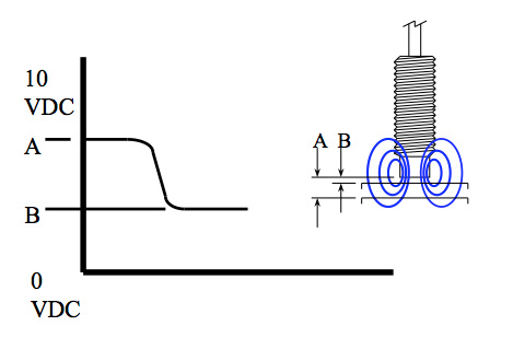
Normal displacement operation
• The sensor uses the portion of the electro-magnetic field radiating from the end of the sensor.
• As the target moves from position A to position B the output voltage decreases.
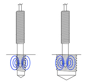
Thread detection using eddy current technology
• Instead of using the axial portion of the electro-magnetic field, thread detection uses the radial portion of the field.
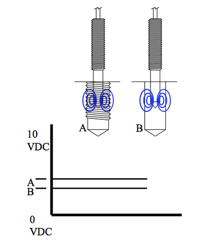
Thread presence/absence operation
• The sensor uses the portion of the electro-magnetic field radiating radially from the sensor.
• An untapped hole results in a lower voltage output than that of a tapped hole.

IN OPERATION
Thread Detection Zone 1
• Sensor in air.
• Output saturated high.
Thread Detection Zone 2
• Sensor enters the tapped hole.
• Radial portion of the electro-magnetic field engages the threaded hole.
• Output begins to decrease.
Thread Detection Zone 3
• Sensor is completely in threaded section of the tapped hole.
• Electro-magnetic field is fully engaged.
• Output indicates pitch diameter of threads.
Thread Detection Zone 4
• Sensor transitions to untapped section of the hole.
• Electro-magnetic field transitions from threads to tap drill diameter.
• Output decreases.
Thread Detection Zone 5
• Sensor’s electro-magnetic field is com-pletely in untapped section of the hole.
• Output indicates untapped hole diameter.
Thread Detection Zone 6
• Sensor’s electro-magnetic field begins to engage bottom of the hole.
• Output continues to decrease as it does in a normal displacement measurement.
APPLICATION CONCERNS
• Thread pitch – Coarse threads are easier to detect. Finer threads require tighter insertion repeatability
• Pitch diameter vs. sensor diameter – Bigger gaps provide less sensitivity. Smaller gaps require tighter insertion repeatability
• Axial insertion repeatability – Long thread length is easier. Short thread lengths require tighter insertion repeatability.
• Radial insertion repeatability – Big hole/small sensor is easier.
Less gap requires tighter insertion repeatability.
• Thermal environmental changes – Sensor temperature changes can/will cause a change in the output.
• Cut vs. cold form threads – Cut threads are easier to detect. Formed threads requires tighter insertion repeatability.
• Base material – As this is an eddy current device, the base material must be electrically conductive.
• Sensor damage potential – Spring-loaded sensor mounts minimize damage potential during operation.
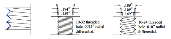
Thread pitch
• Eddy currents induced in the surface follow the contour of the threads.
• Output voltage indicates the average of the major and minor thread diameters, essentially the pitch diameter of the threads.
• The coarser the threads, the greater the voltage difference between tapped and untapped holes.
• Finer threads warrant tighter radial insertion repeatability of the sensor.
Pitch diameter vs. sensor diameter
• Although the output is linear, the sensitivity is greater close in to the sensor and less farther out.
• Too small a gap can cause rubbing between the sensor body and thread ID resulting in irreparable damage to the sensor.
• Too large a gap and eccentricity between the sensor and hole becomes an error source.
• It is best to stay within the published recommendations for the thread size being checked.
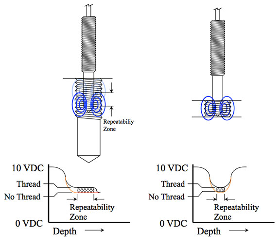
Axial insertion repeatability
• The output changes as the sensor enters the tapped hole.
• If not fully inserted, minor depth changes will result in output changes.
• Longer thread lengths provide best reliability.
• Thread lengths shorter than the electro-magnetic field length require very repeatable axial insertion.
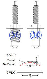
Radial insertion repeatability
• The output changes as the sensor moves laterally in a hole, tapped or untapped.
• Hole/sensor eccentricity can be an error source.
• Better radial insertion repeatability X will provide greater headroom Y resulting in more reliable operation.
Thermal sensitivity
• Spec is 0.05%/deg C
• Output is 0-10 VDC
• With thread voltage @ 4.500 VDC and unthreaded voltage at 4.300 VDC when taught, the switch is set to trip at 4.400 VDC.
• 4.300 VDC x . 05% = .00215 VDC change per degree C. Hence a 10 degree C change in ambient temperature could result in an untapped hole voltage of 4.3215 VDC, now only .0785 VDC from the switch point instead of the original 0.100 VDC.
• At wider gaps, the voltage value is higher resulting in a higher voltage shift, getting even closer to the switch point.
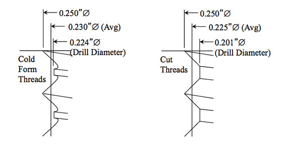
Cut vs. cold form threads
• Hole diameter for cold form threads is larger than cut threads.
• The difference between the hole diameter and average (basically pitch) diameter is much less with cold formed threads.
• Cold working can change the properties of the material somewhat, affecting the sensor output. This is more of a concern with ferrous materials.
• Cold form threads typically can be 60% of full depth vs. 75 % of full depth for the same strength in cut threads. This can reduce the drill diameter to average diameter distance even more.
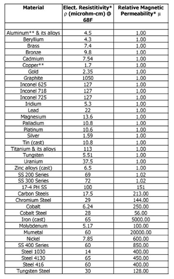
Base material
• The most influential difference is seen between ferrous and non-ferrous material.
• The second major influence is conductivity.
• Within ferrous and non-ferrous categories, ‘teaching’ the sensor the new material is sufficient to accommodate the variation in conductivity.

Sensor damage potential
• The coil in the sensor is only ~0.010” from the OD of the PEEK sensor tip just below the conical section. Exercise care to avoid the sensor tip rubbing on the inside of the hole.
• Plunging the sensor into a broken tap is obviously going to cause irrepairable damage. Using a spring loaded sensor mount will help minimize this potential.
• The sensor and electronics are rated IP67. The cabling in PUR jacketed, and the sensor is made of PEEK and stainless steel. This combination holds up very well to a wide variety of coolants and lubricants.
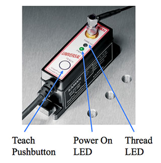
Teaching the ThreadCheckerTM
• Push the teach button once to put the microprocessor in ‘teach’ mode. The ‘Thread’ LED will be yellow and flash rapidly.
• Insert the sensor into a threaded hole, and push the teach button once. The ‘Thread’ LED will be yellow and flash slowly.
• Insert the sensor into an unthreaded hole, and push the teach button once. The ‘Thread’ LED will be red indicating no thread.
• Alternate between threaded and unthreaded holes, and verify the ‘Thread’ LED is green when the sensor is in the threaded hole and red when the sensor is in the unthreaded hole (or not in a hole at all).
• If desired, the polarity of the switched output can be inverted by holding the teach button for 10 seconds.
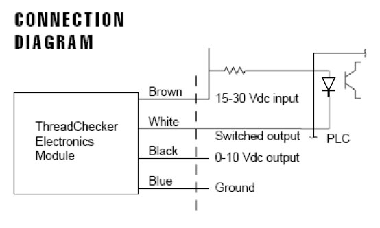
Electrical installation
• Brown – 15-30VDC input
• White – switched output NPN
• Black – analog output
• Blue – ground
• Input power is reverse polarity and short circuit protected
• Switched output 30VDC max, 80mA max, 3KHz
Every application is unique.
Contact Kaman for application engineering assistance. |
